Ac To Dc Converter Circuit Diagram
Ac To Dc Converter Circuit Diagram

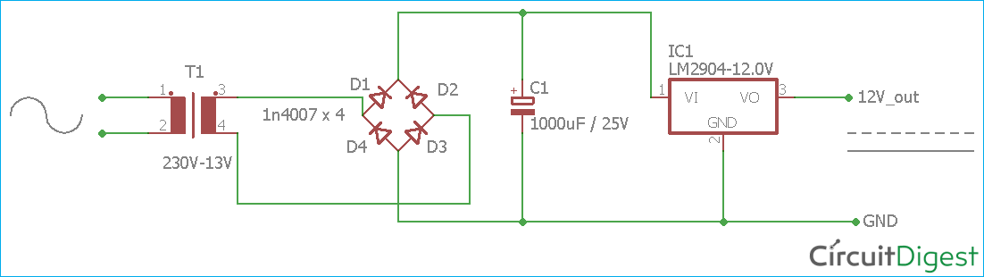
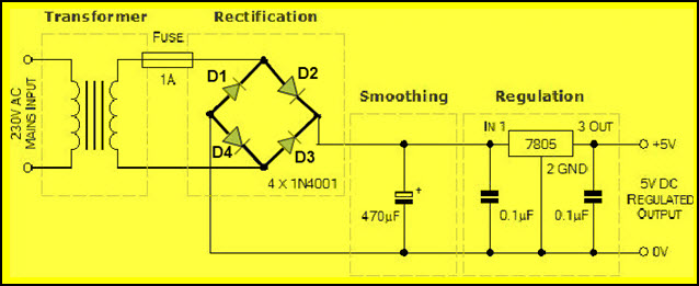
220 230v Ac To 12v 5v Dc Regulated Power Dc Converter Bridge Rectifier Simple Circuit Power Dc Circuit

Circuit Diagram Of A Flyback Ac Dc Converter Download Scientific Diagram

Circuit Diagram Of Proposed Single Stage Ac Dc Converter With Pfc And Download Scientific Diagram
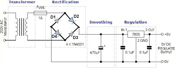
Steps To Convert The 230v To 5v Dc To Powerup The Circuits

Ac To Dc Converter Circuit Diagram
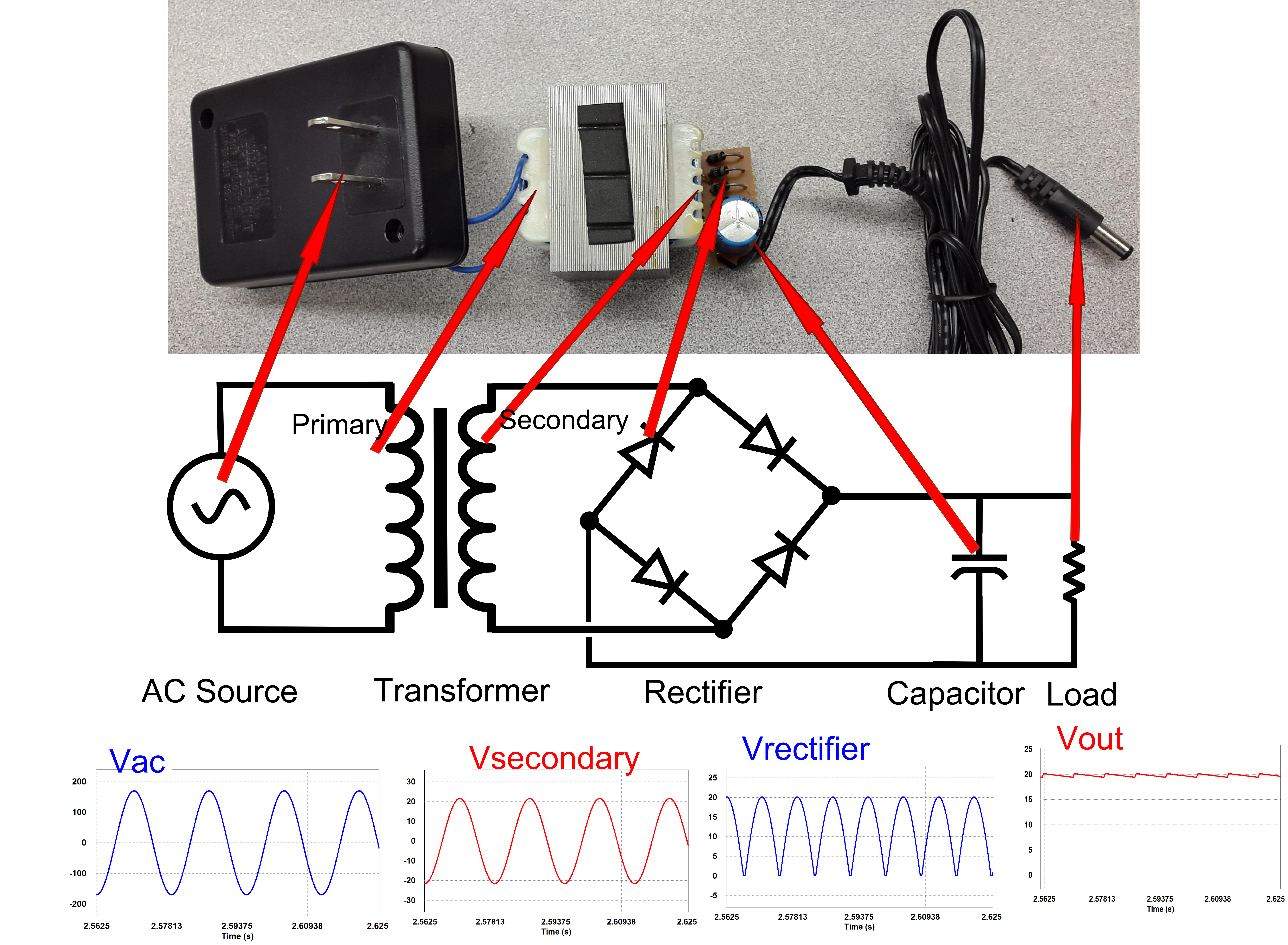
The process is known as rectification since it straightens the direction of current physically rectifiers take a number of forms including vacuum tube diodes wet chemical cells mercury arc valves stacks of copper.
Ac to dc converter circuit diagram. But by using power electronics converter circuits this power can be converted into the required form and range. The input voltage output voltage and frequency and overall power handling depend on the design of the specific device or circuitry. These circuits are mainly used for driving low power ac motors and used in a solar power system. Electrical power supply became as a basic need in our day to day life the power we are availing is 230v 50hz ac supply.
A rectifier is an electrical device that converts alternating current ac which periodically reverses direction to direct current dc which flows in only one direction. Limitations of transformer based ac dc converter circuit. What is dc to dc converter. The inverter does not produce any power.
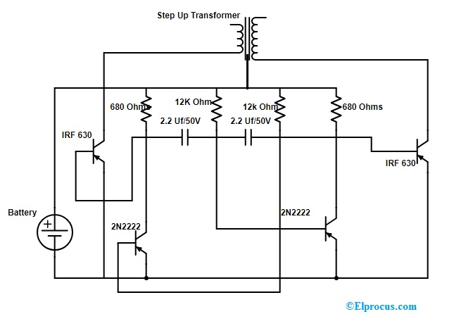
This ac to dc converter circuit is capable of converting an alternative voltage within 70v 260v range into a dc voltage within 180v to 350v dc range so it can be used for 110v and 220v too. A 12v dc to 220 v ac converter can also be designed using simple transistors. Transformer based ac to dc conversion is a common choice where dc is required but it has certain drawbacks. To achieve this voltage conversion we use a mc34161 rectifier as a voltage doubler at low input voltages and as a classic rectifier at high input voltages.
1 any situations where the input ac voltage has possibilities to fluctuate or if the ac voltage drops significantly the output ac voltage across the transformer also gets dropped. A dc to dc boost converter circuit is a circuit that can convert a dc voltage into a larger dc voltage. The power is provided by the dc source. A power inverter or inverter is a power electronic device or circuitry that changes direct current dc to alternating current ac.
So for example you may be able to convert a 5v dc voltage into 30v. The applications of dc to ac converter circuit include the following. The dc to ac converters is used in a vehicle to charge their batteries. Instead of discussing how and why the circuits work some readers focus on the dangerous side of the circuits that involve ac.
When fed dc power the inductor acts as a energy storage device for current. This article consists of a simple dc to dc converter circuit diagram and working of it. It can be used to power lamps up to 35w but can be made to drive more powerful loads by adding more mosfets. A dc to dc converter is an electronic circuit or electromechanical device that converts a source of direct current dc from one voltage level to another it is a type of electric power converter.
Dc to ac converter applications. A dc to dc converter works on the principle of an inductor primarily and a capacitor. The inverter implemented in this circuit is a square wave inverter and works with devices that do not require pure sine wave ac.

Ac To Dc Converter Circuit Diagram

How To Make Ac To Dc Converter At Home Youtube

Circuit Diagram For Simple Ac To Dc Converter Using Bridge Rectifier Electronica

Em 1359 Convert Ac To Dc Circuit Free Diagram

Ac To Dc Converter Multisim Live

Dc Ac Converter Circuit Diagram Download Scientific Diagram
How To Convert 230v Ac To 12v Dc Quora
Ac Dc Converters Disassembling A Linear Power Supply Technical Articles

Simple Ac To Dc Converter Using Bridge Rectifier

Ac Dc Converter Circuit Multisim Live

Where Exactly Does The Ground Line Go In An Ac Dc Power Supply Electrical Engineering Stack Exchange
Steps To Convert Ac To Dc Working Of Ac To Dc Converter

Improving The Efficiency Of Ac Dc Converters Through Synchronous Rectification Tech Info Rohm Tech Web Technical Information Site Of Power Supply Design